DESCRIPTION
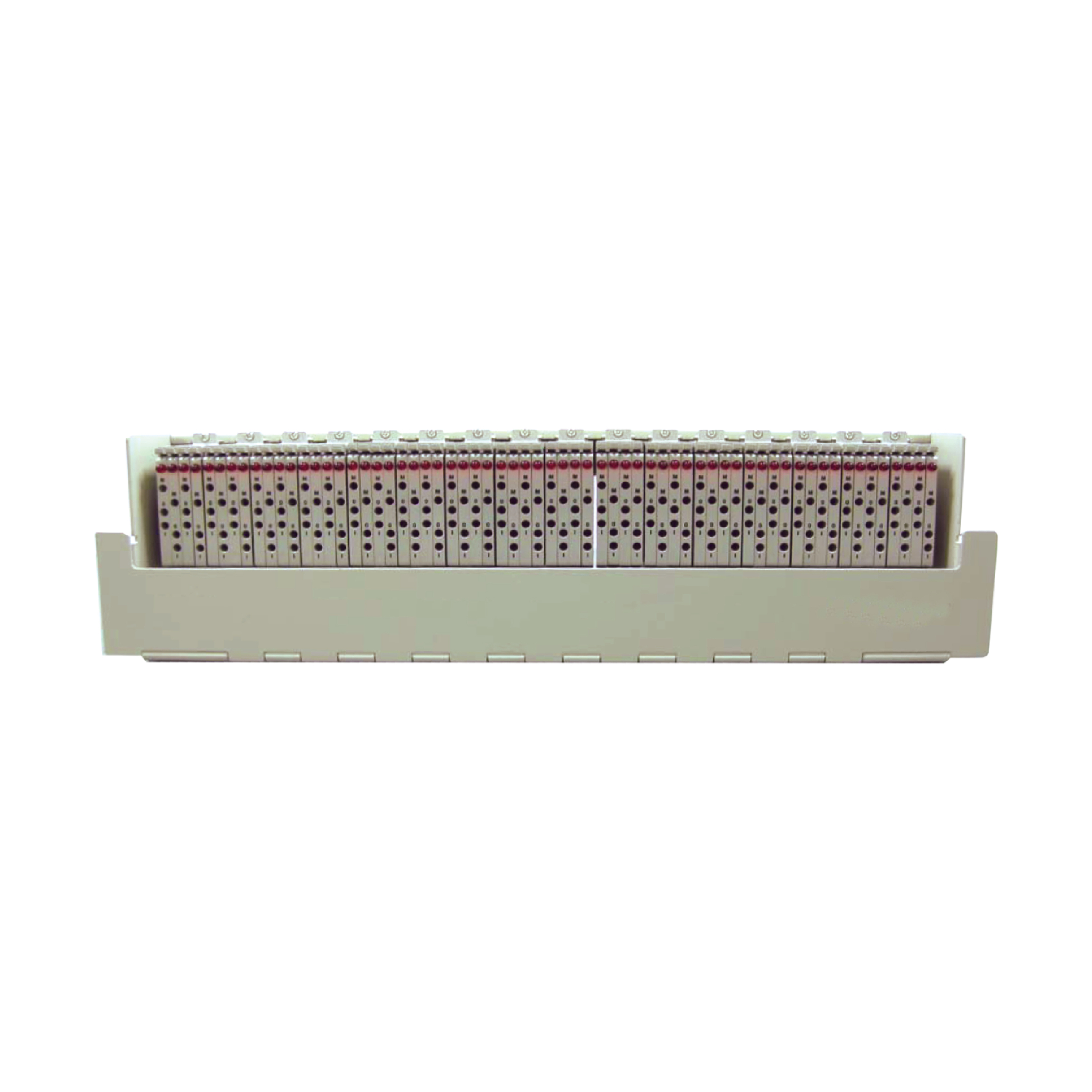
Litech WW7 DSX Pane type 64 circuit 23”, is a centralized termination point for digital equipment at DS1 (1.544Mbps) and E1 (2.048Mbps) digital signal bit rate. DSX Panel allows access point for circuit jumpering, cross-connecting, monitor for input signals & testing, for SDH (Synchronous Digital Hierarchy)networks STMN (N=1/4/16) terminal equipments .
This panel includes 3-port jack access cards, cable tray, red LEDs, and labels. Jacks are rigorously tested with over 20,000 insertions/withdrawals. It guarantees reliability, durability, and quality over time. LEDs flash at both ends of the monitored circuit for 30 seconds, enables quick identification of crossconnected circuits.
Litech WW7 DSX Panel type 64 circuit 23” is modular design, it is capable of high density installation. Each circuit in the DSX-ADC Type 64 circuit 23” panel is independence allow scalable capacity to reduce the initial set-up cost, and for easy maintenance, the independent circuit module can be replaced separately. The panel in 19” (48.3cm) and the 23” (58.4cm) models use the same plug-in, 4-circuit modules. The 19” panel is expandable to 64 circuits, while the 23” panel is expandable to 84 circuits. Panels mount on EIA or WECO equipment racks.

FEATURES
• Litech WW7 DSX Pane type 64 circuit 23” is Modular design capable of high density installation.
• Each circuit in Litech WW7 DSX Pane type 64 circuit 23” is independence for choose the capacity
• Low cost, cost saving
• 10-year warranty (Term And Condition Apply
STRUCTURE
Litech WW7 DSX Module Type Digital Distribution Panel necessary quantity of circuit module and optional accessories as following:
1.0 Chassis
1.1 The properly space for 64-circuit module (23”).
1.2 The material is rustproof steel.
1.3 Tinned brass terminal pins are provided on the bottom of the front for wire wrapping connection, cable holders are located in both side, the cable tray in the front and rear and circuit name plate sheet are provided for cable storage and management.
1.4 Power pin for –48V DC and terminal pin for grounding (GND) on the top side of the rear.